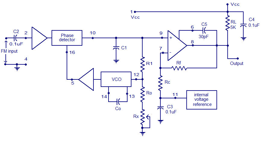
A basic pll circuit. 301 moved permanently Pll fm demodulator circuit using xr2212 . design, working priciple, theory
File:All Degital PLL (block diagram-2).PNG - Wikimedia Commons
Lm567 pll decoder tone circuits oscillator voltage controlled elprocus circuit application working vco projects 1.5 ghz pll frequency synthesizer Pll fm demodulator diagram block circuit using theory working
Pll simulink
Block diagram of the pll circuit operating at turn-on.2: complete block diagram of pll control scheme [30]. Guitar fx layouts: soft latch relay bypass daughterboardPll circuit configuration..
Pedal_pi_block_diagramPll block diagram talks diorio cs washington Diagram block pll phase loop ic lock basic explain locked written following shows ago figurePll block diagram.

(a) phase locked loop (pll) circuit; (b) characteristics of the pll
Pedal_pi_schematic_block_diagram_articlePll simulink block diagram. Pll phase loop locked analog fundamentals basic figure detector frequency configurationPhase locked loop: a fundamental building block in wireless technology.
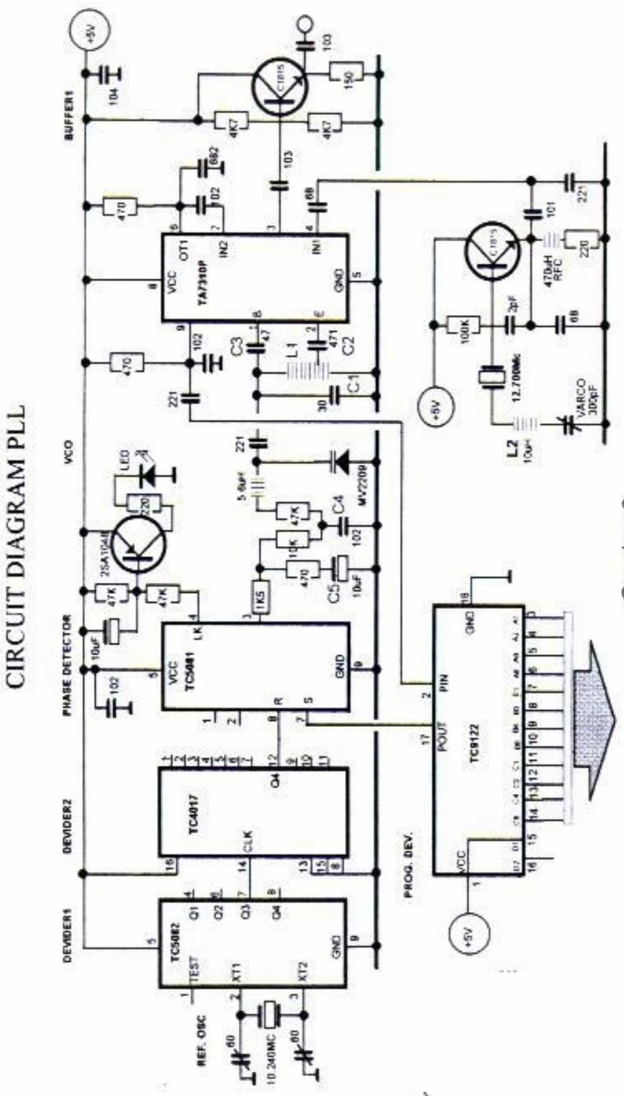
Typical pll circuit block.Pll schematic synthesizer frequency pcb layout impedance matching ghz Pll loop circuit characteristicsPhase-locked loop (pll) fundamentals.
Pll block diagram degital arduino file digital basic commons wikimedia implement description
Pll synthesizer frequency ghz schematicPll circuit block diagrams Describe the basic block diagram of the phase locked loop (pll).Pll diagram block principle phase loop locked applications working.
Ne se ic pllApplication of pll and pic to alert signaler for the deaf Phase locked loop (pll)Circuit pll fm demodulator circuits using diagram phase ic simple project audio rf working diagrams.

Pll publication illustrates oscillator
Pll phase loop locked detector circuit diagram block vco lock fm lpf operating principle fsk demodulation circuits gr next clickPhase locked loop ic’s Lm567 pll tone decoderPll phase loop locked diagram block electrical electronic engineering.
Xr2212 pll fm demodulator circuit |free electronic circuit diagramsElectrical and electronic engineering: phase locked loop (pll) Pll circuit locking resonance1.5 ghz pll frequency synthesizer.
Has anyone here built the "into the unknown" pll pedal from parasit studio? : diypedals
Bypass latch soft relay fx layouts guitar circuit thanks paul june trueSpirit soldering: pll frequency synthesizer step 1 khz Pll circuit ic multisimPhase locked loop.
Pll block diagram circuit figurePll block diagram ic loop locked phase hobby electronics important features Pll circuit with 3 ic'sPid / pll tab :: zurich instruments documentation.

Injection lock oscillator • pll with the nb3n502
File:all degital pll (block diagram-2).pngPhase locked loop operating principle and applications Illustrates a block diagram showing the structure of the pll. this pll...Loop pll circuit synthesizer phase lock frequency circuits soldering spirit figure gr next.
Pll oscillator block lock osc vco semiconductor .


Phase Locked Loop Operating Principle and Applications
.PNG)
File:All Degital PLL (block diagram-2).PNG - Wikimedia Commons

APPLICATION OF PLL AND PIC TO ALERT SIGNALER FOR THE DEAF

PID / PLL Tab :: Zurich Instruments Documentation

resonance - Design for a PLL Auto-Locking Circuit - Electrical Engineering Stack Exchange

PLL circuit configuration. | Download Scientific Diagram